We use cookies from thirth parties to inprove your experience and our services. If you do not close this window we understand that you allow its use. For more information about cookies click here
Cerrar

 | Download article | Times downloaded:
132
| Download article | Times downloaded:
132
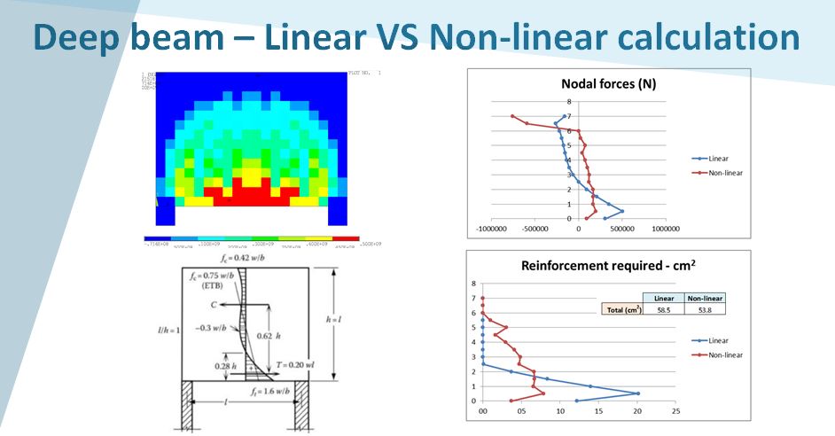
When doing a hand-made calculation of a structure or when modelling it in a finite element program, it is needed to do some modelling assumptions. For example, it is quite common to model the structure at the neutral axis. This type of modelling will end up with bigger spans than the real ones and loose of stiffness for some cases. However, the modelled span and the design bending moment can be considered differently, different from the neutral axis, in function of the support conditions. In this article it will be summarised the EC-2 requirements/recommendations for span modelling and bending moment calculation. It will also be compared against hand-made calculations and non-linear ones, using IDEA StatiCa (thanks to Construsoft for their support).
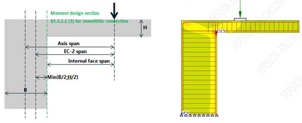
Figure 1. Span and bending moment calculation (left) – Non linear results (right)
The first point of this article is to present and summarise the EC-2 requirements for the effective span definition provided in section §5.3.2.2 and presented in the following image:
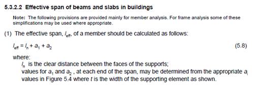
Figure 2. Section §5.3.2.2 (1) of EC-2 – Effective span definition
The following figure defines the different parameters required to calculate the total span, in function of the different support conditions:
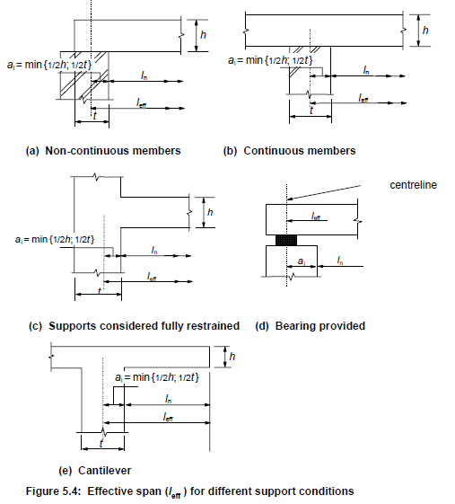
Figure 3. Figure 5.4 of section §5.3.2.2 (1) of EC-2 – Effective span definition
In general, except for the case where a bearing support is provided, the span has to be considered as the distance between the inner faces plus a value which is calculated as the minimum between the thickness of the support and the thickness of the connected beam/slab.
Additionally, there is an important point in the same section §5.3.2.2, where it is specified that when the connection between the slab and the supports it is monolithic, the critical moment has to be calculated at the face of the support:
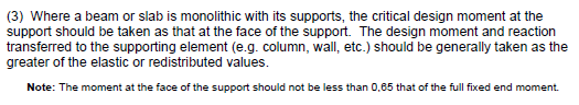
Figure 4. Section §5.3.2.2 (3) of EC-2 – Critical design moment section
This is only applicable when the connection between the supports and the slab is monolithic.
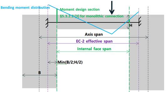
Figure 5. Section §5.3.2.2 (3) of EC-2 – Effective span and critical design moment section
In any case, the following rule could be applied:
-EC-2-Bending-moment-reduction-where-no-rotation.png)
Figure 6. Section §5.3.2.2 (4) of EC-2 – Bending moment reduction where no rotation restraint produced by the support
This means that if the modelled span is from axis to axis and the supporting support does not provide any rotation restraint, design bending moment could be reduced following the above formula. Sometimes it is difficult to prove that the support does not provide any restraint to the rotation as it depends on the support stiffness. The EC-2 provides as an example a wall but depends, for example, on the height and thickness of this wall.
Calculations performed: spans, model and loads definitions
a) Possible spans
As explained above, different spans can be defined in function of the support conditions:
· Axis span: distance between the load and the support axis or the distance between the two support axis. This is the most common one, used generally for finite element models
· EC-2 span: defined following §5.3.2.2. It is similar for the previous one when the thickness of the two connected elements (H and B) are equal but differs when these are different
· Internal face span: distance between the load and the support internal face or the distance between the two supports internal faces. This is important when there is a monolithic connection between the slab/beam and the support
These spans are reflected in the following figure:
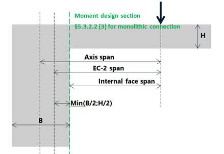
Figure 7. Different span definition used in this article
In this article we will calculate the different moments, for a cantilever beam, produced by the 3 possible spans presented above and compare them with the results produced by the non-linear calculation.
b) Load cases
Two different loads will be used: a punctual one and a uniform distributed one:
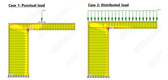
Figure 8. Load cases definition
c) Model geometry, reinforcement and materials
The calculated beam is a 0.5x0.4 beam reinforced with 4C20 on the top and bottom face, closed stirrups C12@200 for the shear, supported by a variable width support (0.3m, 0.5m, 1m and 1.5m):
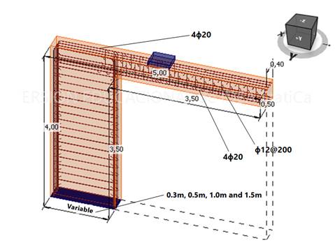
Figure 9. Geometry and reinforcement definition
A full non-linear for the concrete (C40, fcd=fck/1.5=26.6MPa) and steel (fyd=fyk/1.15=434MPa and k=1.08) materials, with yielding cracking and crushing properties. This will be performed with the software IDEA StatiCa Detail. The following figure presents the material laws, for further details refer to IDEA StatiCa material definition:
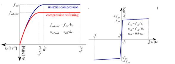
Figure 10. Non-linear material laws
Results
a) Results: Interaction diagram
The first point is to calculate the maximum resisted bending moment of the beam considering the geometry and reinforcement provided above and the EC-2 diagram simplifications (equivalent rectangular stress distribution (C40, fcd=fck/1.5=26.6MPa) and reinforcement considered yielded (fyd=fyk/1.15=434MPa, k=0). As presented in the following figure, calculated with the Interaction diagram online tool of Prontubeam, the maximum resisted bending moment, without any tension/compression on the section, is 228kN.m:
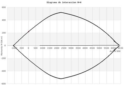
Figure 11. Interaction diagram for the studied beam – 228kN.m Maximum resisted moment with N=0
b) Results: handmade calculations
The following table presents the hand-made calculated moments for each of the 3 spans presented above for each of the support thickness ad load configurations. These are compared against the resisted moment 228kN.m, to calculate the ratio between the acting moment and the resisted one:
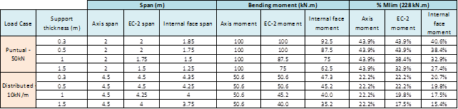
Figure 12. Hand-made calculated moments for each load type, support thickness and span definition
(*) Nota: EC-2 moment refers to the moment calculated following the EC-2 §5.3.2.2 figure 5.4 span definition
These results will be, later, compared against the non-linear model calculation to extract some conclusions.
c) Results: Non-linear model
The following picture presents the results obtained for the different cases calculated with the non-linear model. In particular, presents the ratio between the stress on the reinforcement for the given load and the maximum resisted stress (fyd=1.08*500/1.15 – Refer to IDEA StatiCa material law, bilinear with inclined upper branch):
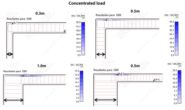
Figure 13. Non-linear results – Punctual load – Ratio stress/limit stress on the top reinforcement
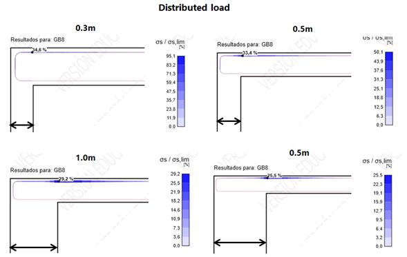
Figure 14. Non-linear results – Distributed load – Ratio stress/limit stress on the top reinforcement
One common point appears in all of them: the maximum is produced at the internal face of the support, following §5.3.2.2 (3) of the EC-2. These results are summarised in the following table, compared with the hand-made calculated moments, for each of the considered spans:
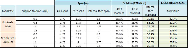
Figure 15. Comparison - Non-linear results – Hand-made calculated results
As it can be observed again, the results confirm that the design bending moment has to be considered at the face of the support. The differences between the hand-made results and the IDEA StatiCa ones comes from the fact that the maximum resisted moment has been calculated equal to 228kN.m considering a bilinear steel law with horizontal plasticised branch while IDEA StatiCa permits to reach fyd=1.08*500/1.15 with plasticised strains.
Maximum bending moment for the 1m thick support case – Theoretical vs. Non linear
The maximum resisted bending moment and its applied load is calculated using IDEA StatiCa and compared to the maximum one calculated with the interaction diagram.
Two values are calculated, one considering the concrete and steel with non-linear material laws presented below and a second one considering the classical bilinear material laws.
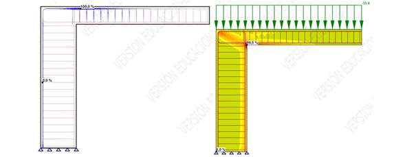
Figure 16. Non-linear results – maximum admissible distributed load considering non-linear material laws
The following results are found:
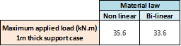
Figure 17. Non-linear results – maximum admissible distributed load for both material possibilities
The following table presents the calculated bending moments for each of the spans when applying both loads obtained with IDEA StatiCa:
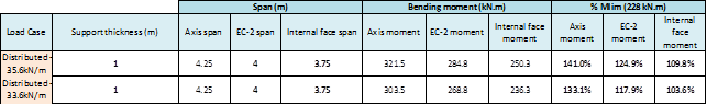
Figure 18. Hand-made and non-linear results – Comparison for the maximum limit load
As it can be seen, when the load of 33.6 kN.m is applied, which corresponds to the case where bilinear material load is considered, the bending moment at the face of the support is 236kN.m which is quite similar to the maximum resisted one calculated with the interaction diagram (228kN.m). It is proved that if the bending moment is calculated at the axis of the support or considering the theoretical span given by the EC-2, this gives an over-dimensioned bending moment which will not exist in reality if the connection between support and slab is monolithic. This confirms the EC-2, section §5.3.2.2 (3).
Conclusions
The following conclusions are extracted from this article:
· In general, except for the case where a bearing support is provided, the effective span has to be modelled as the distance between the inner faces plus a value which is calculated as the minimum between the thickness of the support and the thickness of the connected beam/slab.
· In section §5.3.2.2 it is specified that when the connection between the slab and the supports it is monolithic, the critical moment has to be calculated at the face of the support. This is only applicable when the connection between the supports and the slab is monolithic
· In this article it has been proved that, as proposed by the EC, when the connection between the support and the slab/beam is monolithic, the bending moment has to be calculated at the internal face of the support
· If the modelled span is from axis to axis and the supporting support does not provide any rotation restraint, design bending moment could be reduced following the §5.3.2.2 (4) formula. Sometimes it is difficult to prove that the support does not provide any restraint to the rotation as it depends on the support stiffness. The EC provides as an example a wall but depends on the height and thickness of this wall
It is noted that all the information here presented is to be considered for information only. It is the engineer in charge of the calculation who needs to verify the calculation and ensure that is complient with the project standards.
| Download article | Times downloaded:
132