We use cookies from thirth parties to inprove your experience and our services. If you do not close this window we understand that you allow its use. For more information about cookies click here
Cerrar

 | Download article | Times downloaded:
692
| Download article | Times downloaded:
692
In this article it is proposed the possible strut and tie models for a beam section thickness change under different types of efforts. This is a zone of discontinuity, it is a D region. These models will be, later on, verified using truss models.
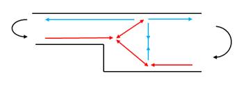
Figure 1. Example of strut and tie model in a section thickness change
The following load cases will be studied in this article for the D region of a beam thickness change:
- Positive moment
- Negative moment
- Positive moment + Shear
- Negative moment + Shear
1.1 Section thickness change – Positive moment
The following picture shows the strut and tie model proposed for the change of the beam thickness where only a positive moment is applied, without shear:
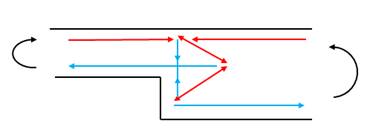
Figure 2. Strut and tie model section thickness change – Positive moment
A truss model is used to verify the previous proposed model. A positive moment is applied on the right side and two simple supports are placed on the left side to simulate a fixed beam to ensure the positive moment along the beam, and especially in the section thickness change:
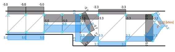
Figure 3. Truss model for the strut and tie model section thickness change – Positive moment
As it is checked, diagonal struts are modelled, but, as there is no shear force, they have no efforts. The fact that there is a D region, a sudden change of thickness, produces and additional tie that needs to be reinforced with vertical stirrups, with an equivalent area as the required longitudinal one to resist the moment. The first strut, the one on the right, close to the moment application, does not need to be considered, as it is produced due to the way the moment is applied.
1.2 Section thickness change – Negative moment
The following picture shows the strut and tie model proposed for the case where a positive moment is applied in the section, with no shear:
Figure 4. Strut and tie model section thickness change – Negative moment
A truss model is used to verify the previous proposed model. A negative moment is applied on the right side and two simple supports are placed on the left side to simulate a fixed beam to ensure the negative moment along the beam, and especially in the section thickness change:
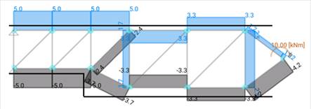
Figure 5. Truss model for the strut and tie model section thickness change – Negative moment
Like in the last case, the diagonal struts have no efforts as there is no shear force. It is also verified that a tie appears before the section thickness change, but in this case, it appears slightly shifted to the right, further to the D region. This tie needs to be reinforced. The first tie, the one on the right, close to the moment application, does not need to be considered, as it is produced due to the way the moment is applied.
1.3 Section thickness change – Positive moment + Shear force
The following pictures show the proposed strut and tie models for the case where a positive moment with shear force is applied on the same time. Different models are proposed, we encourage the reader to share, in the comments section, which is, in his/her opinion, the most suitable one:
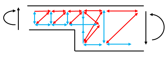
Figura 6. Strut and tie model section thickness change – Positive moment and shear force – Option 1
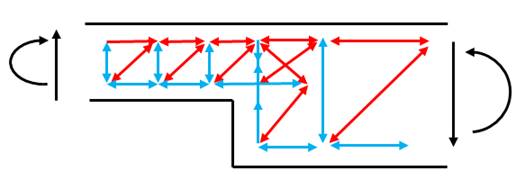
Figure 7. Strut and tie model section thickness change – Positive moment and shear force – Option 2
The previous two options are modelled using a simply supported truss beam with a punctual load applied on the middle to have the desired efforts, positive bending moment with shear force at the same time. The following picture shows the whole modelled beam and the loads applied. Only the Option 1 is shown but the model would be equivalent for the Option 2, later on both options are shown in detail:
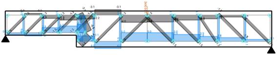
Figure 8. Truss model for the strut and tie model section thickness change – Positive moment and shear force – Option 2
It is interesting to see how this model captures the loss of rigidity on the side where the thickness change is produced. This effect can be seen in the vertical ties as, out of a total of 2kN, 0.9kN goes to the side where the D region is placed while 1.1kN goes to the other side.
Let’s zoom in where the section thickness change is produced. In this case, both options are shown (Option 1 and Option 2 of the pictures 6 and 7):
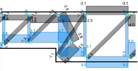
Figure 9. Detailed strut and tie model section thickness change – Positive moment and shear force – Option 1
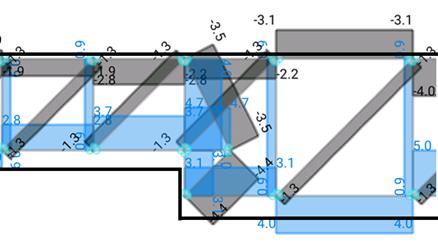
Figure 10. Detailed strut and tie model section thickness change – Positive moment and shear force – Option 2
As it can be seen, on each option, the force on the tie before the section change has a different value. A third option is proposed, it is the Option 2 but we have separated the effect of the moment on the section change and the shear force effect. Like this, it can be verified how much is the required reinforcement due to each effort (bending and shear) on the D region:

Figure 11. Detailed strut and tie model section thickness change – Positive moment and shear force – Option 3
It is checked that the Option 3 (which is similar to the Option 2) has a total vertical tie of 4.0kN, 0.9kN comes from the shear force and 3.1kN comes from the bending moment. However, in the Option 1, the whole vertical tie before the section change has a total value of 3.1kN. We also have to compare the horizontal tie produced on the section change. Its value is 3.7kN for the Option 1 while n the Option 2 has a value of 4.7kN. Theoretically, the best strut and tie model is the one whose strain energy is the lowest one, in other words, the one whose sum of the forces of the ties multiplied by their length is the lowest one. Let’s do the math for both Options:
Option 1: 3.4kN x 3m + 3.7kN x 1m: 13.9kN.m
Option 2: 3.1kN x 1m + 4kN x 2m + 4.7kN x 1m = 15.8kN.m
According to these results, we could say that the Option 1 would be the correct one. We encourage the readers to comment on the comments section after the article.
1.4 Section thickness change – Negative moment + Shear force
The following picture shows the proposed strut and tie model for the case with negative bending moment and shear force on the D region:
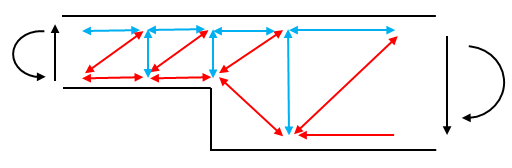
Figure 12. Strut and tie model section thickness change – Negative moment and shear force
In this case the model and the calculation are easier as there is only one possible solution. It is verified that the tie before the change of section thickness is increased by the effect of this change of thickness. This is the same effect as the case with only bending moment applied shown before:
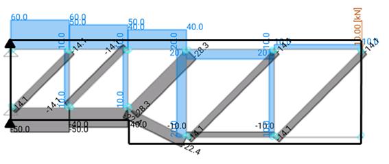
Figure 13. Truss model for the strut and tie model section thickness change – Negative moment and shear force
| Download article | Times downloaded:
692