Utilizamos cookies propias y de terceros para mejorar tu experiencia y nuestros servicios. Si continúas navegando consideramos que aceptas su uso. Puedes obtener más información sobre cookies
aquí
Cerrar
Home
Spanish
English
Handbook
Structures handbook
Interactive handbook
Structural steelwork handbook
Specific weight handbook
Cross-sectional reinforcement handbook
Anchorage length handbook-EC-2
Concrete verifications
Interaction diagram
Shear resistance
Punching resistance
Torsion resistance
Cracking moment and neutral axis
Design anchorage length following EC-2
Shrinkage calculation - EN 1992-1-1
Engineering tools
Web searcher
Tools searcher
Unit converter
Civil technical vocabulary translator
Excel-Formulas translator
Vibration equations 1DOF
Publications
Articles
Enginnering in the network
Civil engineering books
Lists
About us
Home
Engineering in the network
Picture
Spanish version
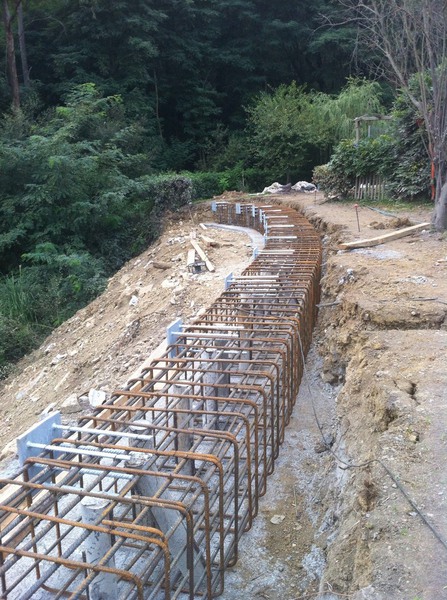
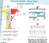
Frame corner reinforcement arrangement performance in positive bending (II)
May , 30th 2023 |
Via: Francesco Marchetto (Linkedin)-www.msb.se |
Seen: 1171 times
This is a more recent study of the one published
in this other post about reinforcement behaviour in frame corners under positive bending moment
.
Previous picture
Frame corner reinforcement arrangement performance in positive bending
Next picture
Methods to increase the safety factor of soil slopes
If you like it, share it!
Share in Facebook
Share in Twitter
Share in Google+
Other civil engineering pictures that you might like:
Type of piles
Slope stabilization through micropiles
Precast pile driving
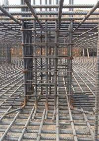
Concrete column reinforcement detail
¿Do you want to publish in Prontubeam? Send us your name, mail and subjet of the article. We will get in touch with you as soon as possible
Full name:
Email adress:
Subjet of the article:
I am not a robot:
Cargando comentarios...
Subscribe: Prontubeam in your mail
Name:
Email:
I accept the privacy policy
Last published engineering pictures
Shear stress at a joint-Elastic VS Plastic-FE Model
Read 39 times
Shear stress at joint-Example calculation for a distributed load
Read 76 times
Flat plate – 2 edges simply supported and 2 edges fixed – efforts and displacements
Read 220 times
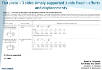
Flat plate – 3 edges simply supported and one edge free – efforts and displacements
Read 314 times
Flat plate – 3 edges simply supported and one edge fixed – efforts and displacements
Read 305 times
TOP 5 engineering pictures of the month
Shear stress at joint-Example calculation for a distributed load
Read 76 times
Shear stress at a joint-Elastic VS Plastic-FE Model
Read 39 times
Simply supported beam deflexion/rotation angles. Do you have to review?
Read 34 times
One side fixed beam bending moment. Do you have to review?
Read 30 times
Shear stress at joint-Example calculation for a point load
Read 22 times
Prontubeam - Verify, calculate, check... the Civil Engineering starts here.
This website has been created by Carlos Corral. More information about cookies
click here
The author of this website is not responsible for any possible error in the formulation used. The user has to verify all the results by his own.