We use cookies from thirth parties to inprove your experience and our services. If you do not close this window we understand that you allow its use. For more information about cookies click here
Cerrar

 | Download article | Times downloaded:
787
| Download article | Times downloaded:
787

In my previous publication #1 I was checking correlation between hand calculations, FEA and experiment results of static beam deflection. This time I wanted to check something more demanding – buckling.
I kept my standard of experiments, it means: an analytical solution, a numerical solution FEA, and experiment and a comparison. The goal of this study was to verify possibility of buckling of a solid rod with Euler linear theory usage.
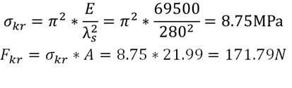
I started from building a test stand. I spent some hours on thinking, what components can I use to assembly a homemade strength machine. Of course I could contract out experimental procedure to laboratory or buy machine, but I wanted to prove myself, that I can do everything by my own at home conditions. After spending some days on exploring web auctions of car components, pneumatic and steel accessories and making some hand calculations I created by my own machine visible in the figure below:
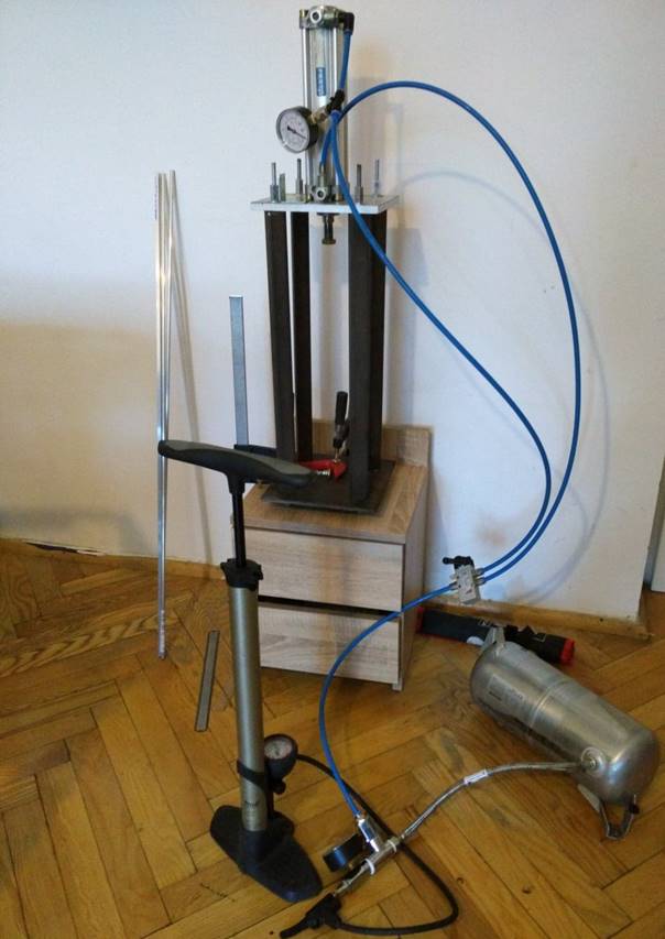
Main components of machine are a pneumatic two way actuator and a hose, a control valve, square steel profiles, a pressure chamber from car’s suspension, a pump and manometers.
Like in my previous experiment, this time also material's data were a little bit problematic, because detailed information was very hard to get – specimens were bought in DIY store. But to perform Euler linear buckling calculations I could use some approximations. Material used was aluminium alloy PA38.
First point of analysis was checking the critical slenderness of the material lambda crit:
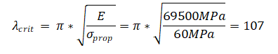
Young Modulus E is a material constant, so it is easy to choose it’s value. It is almost the same for all aluminium alloys. Proportionality limit was not so obvious, because it is strongly connected e.g. with heat treatment. For PA38 proportionality limit fits in range 60 – 160MPa. I assumed, that I had the weakest alloy with 60MPa proportionality limit. I received 107 of slenderness. For 160MPa critical slenderness is equal 65.5
Linear Euler buckling theory works only for slenderness value higher than critical, so for experiment I had to choose geometry dimensions, which respected critical slenderness. I used solid circle rod with 350mm of length and 5mm of diameter. For this geometry we have slenderness lambda s as below:
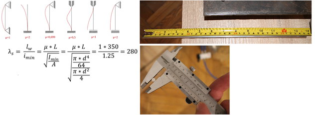
Slenderness ratio 280 > 107 and 65.5, so Euler theory is working for all range of proportionality limits of PA38 for specified geometry.
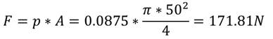
The next step was to calculate critical stress and force as below:
To perform FEM analysis I decied to use demo version of Strand7 software, which allows to perform some simple cases for free. I created boundary conditions, which corresponded to conditions used in analytical solution. Column was built with five 1D elements. I applied 100N compression force in vertical direction like in figure below(gif):

After solving igenvalue problem, solver returned multiplier = 1.7183. After multiply it by compression force I received critical force as below:
![]()
The last step was performing an experiment. Piston in actuator had diameter d = 50mm. To create ~172N of force I had to create ~0.0875MPa in my pressure system. It is equal to ~0,88 bar
Results of the experiment below:

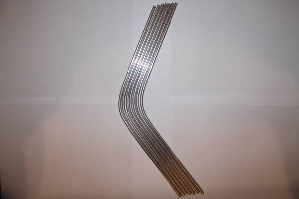
I recived buckle shape of rod at around 0.9 bar ~0.09MPa. Close to 1 bar of pressure, rod damaged in nonlinear way. I recorded a video to illustrate it more detailed. You can see it below (click on the picture to go to the video):
I did several tests to check repeatability of my procedure and machine. Below you can see some specimens after tests:
Summary of analysing critical compression force:
Relative errors of my analysis
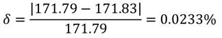
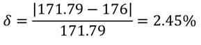
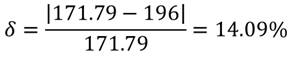
Relative error between analytical solution and experiment was in the range between ~2.5-14%
Copy Rights reserved
Michał Szulewski
CAE Engineer
Visit my profile on linkedin https://www.linkedin.com/in/michalszulewski/
| Download article | Times downloaded:
787